Wiring Recommendations

Internet access discussion, including Fusion, IP Broadband, and Gigabit Fiber!
54 posts Page 5 of 6
by ankh » Fri Aug 30, 2013 7:18 pm
> pictures
Please, definitely that'd help. Good advice here, thank you. (The cable with the modem fell a bit short, but maybe I can find a longer one or move some things around)
by polpo » Sun Sep 01, 2013 2:40 pm
So here's pictures of my NID. We're technically not supposed to be monkeying around with the left side of the NID, so, uh, be careful, YMMV, you didn't hear this from me, for entertainment purposes only, etc.

Image
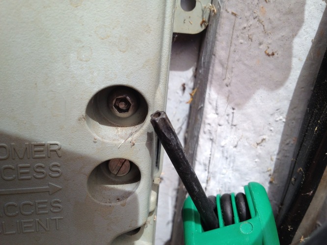
To get into the NID, you need a security hex bit. A security torx bit, which is what I have, also works. I got it at OSH. Once the screw is loose, push the tab on the right side of the NID to open the cover.

Image
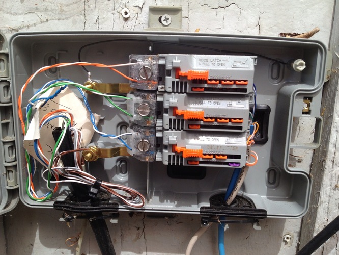
Here's the inside of my NID, which has three lines. The top two are normal line modules, and the bottom one is a DSL filter module. I use the bottom two for my bonded Fusion setup, but only have one filter because I only use the first line for POTS voice. The top one used to have AT&T UVerse on it. I kept it hooked up in case I ever resubscribe.

Image
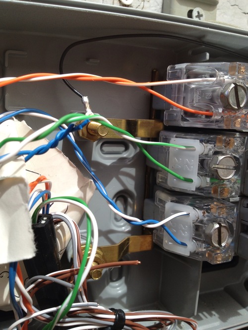
On the left side are the station protectors, where the pairs from the phone company come in. They go in without being stripped. Loosen the screw there, insert the wires until they hit the back of the protector (you should be able to see them through the clear cover), then tighten the screw.

Image
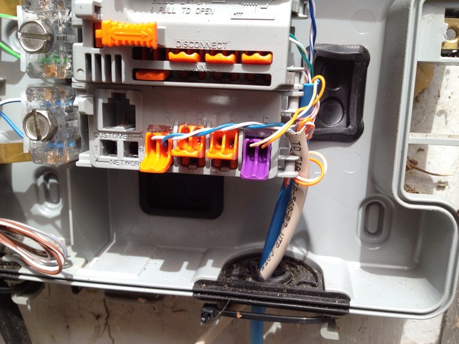
Here's my DSL filter module with the cover off. Put your wires (stripped about 3/8") in the holes and push down on the tabs. DSL home run connects to the purple tab, voice lines on the orange ones. Pretty simple.

If you want to remove a line module, just pry up under the left side under the station protector. There's a grounding lug underneath that holds it in, and there's not much friction holding it in. But in your case, ankh, if you have room in your NID maybe you should leave your existing line module and put the DSL one underneath. Then you can just move the wires down.
by John Lin » Fri Jan 17, 2014 4:14 pm
I have a question on the line modules, as I noticed unlike the type of modules which has a RJ11 cable in the jack when it's normally connected and unplugging it will allow using the test jack which basically disconnects the inside wiring. How do you use the test jack and disconnect the inside wiring? Do you have to push the tabs up to disconnect the other cables?
by polpo » Fri Jan 17, 2014 4:29 pm
Opening the line module door disconnects the inside wiring from the network. Metal contacts in the module door go inside the square holes marked T and R and bridge the network (bottom) and customer (top) sides. Also, pushing the tabs up will disconnect each individual line from the line module. See this PDF for more info.
http://csmedia.corning.com/CableSystems ... 02-338.pdf
by John Lin » Fri Jan 17, 2014 5:21 pm
That makes more sense, Am I correct that the line module door actually has a RJ11 plug that goes into the jack? Seems like basically, instead of having a short cable going into the jack like the older NID's, they eliminated the cable portion. On the station protectors, how does it actually contact the wires? Does it just pierce through the insulation of each wire when you insert it? Also, is that a UNI-3003 model for the NID box? Thanks.
by polpo » Mon Jan 27, 2014 1:45 pm
John Lin wrote:That makes more sense, Am I correct that the line module door actually has a RJ11 plug that goes into the jack? Seems like basically, instead of having a short cable going into the jack like the older NID's, they eliminated the cable portion. On the station protectors, how does it actually contact the wires? Does it just pierce through the insulation of each wire when you insert it? Also, is that a UNI-3003 model for the NID box? Thanks.
No, nothing goes in the RJ11 plug. Two prongs go in the square holes and bridge the top and bottom sides to complete the circuit. You can see the prongs in this image: http://csmedia.corning.com/CableSystems ... 13U2_A.jpg
On the station protectors, it pierces the insulation when you tighten the screw. Yes, it's a UNI-3003 model.
by vincepoy » Tue Feb 25, 2014 1:28 pm
AT&T replaced my old NID with the UNI-3006, the 6 line version of the box you have and also ran a new 6 pair cable to replace the existing 2 pair cable. The network modules are hooked up the same way as yours, the white on top and solid color on the bottom but it seems my telephone line tester reports at the test jack as reverse polarity on all my active lines. Do you know if your polarity is correct as it seems when I had two lines, the first one was reversed and all the guy did was change it at the box instead of the other end. The 2nd line is correct when it was installed a month ago.
by virtualmike » Tue Feb 25, 2014 9:08 pm
vincepoy wrote:... my telephone line tester reports at the test jack as reverse polarity on all my active lines.
Unless you're using a tone telephone that's more than 15 years old, it shouldn't cause any issues. Old touch-tone telco phones from the 60s, 70s, and early 80s had diodes in the tone generators that worked only with correct polarity, but newer phones (and other devices) work just fine regardless of polarity.
by vincepoy » Wed Feb 26, 2014 8:15 pm
virtualmike wrote:
vincepoy wrote:... my telephone line tester reports at the test jack as reverse polarity on all my active lines.
Unless you're using a tone telephone that's more than 15 years old, it shouldn't cause any issues. Old touch-tone telco phones from the 60s, 70s, and early 80s had diodes in the tone generators that worked only with correct polarity, but newer phones (and other devices) work just fine regardless of polarity.
Good point. What's a good way to test touch-tone phones from the 70s and early 80s as I do have a Western Electric Trimline connected. I bought one of the telephone line testers from the hardware store a few years ago and it has a modular plug and also a short straight wired RJ11 cable with only pins 3 & 4 connected so not sure as it can always be the cable supplied that's the problem since the thing might require reverse pin cable for it to work correctly. I have tried opening it but have had no success so far. How would one test the polarity at the NID using a multimeter?
by virtualmike » Wed Feb 26, 2014 10:13 pm
vincepoy wrote:Good point. What's a good way to test touch-tone phones from the 70s and early 80s as I do have a Western Electric Trimline connected.
Plug it in, pick up the handset, and press one of the numbered buttons. If a tone is emitted and dial tone is broken, then the phone will work on the line as it currently is configured.
vincepoy wrote:How would one test the polarity at the NID using a multimeter?
There are many web sites that explain basic POTS principles and provide the voltages to find on the tip and ring wires.
54 posts Page 5 of 6

Who is online

In total there are 90 users online :: 0 registered, 0 hidden and 90 guests (based on users active over the past 5 minutes)
Most users ever online was 999 on Mon May 10, 2021 1:02 am

Users browsing this forum: No registered users and 90 guests